Why? No more burned out bulbs, less power draw (trivial, really - the signals are not ON much).
Really, I was at Princess Auto (I think Harbour Freight is pretty much the same stuff in the USA) and I saw these marker LED units for four bucks each:
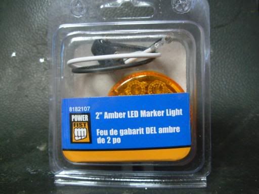
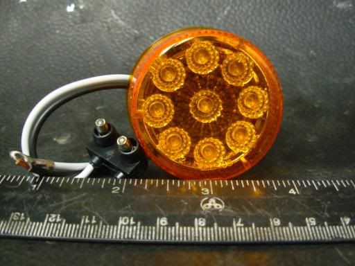
with this stuff included, a marker light and plug-in wiring harness, you can see it is two inches diameter:
This was my turn signal assembly:
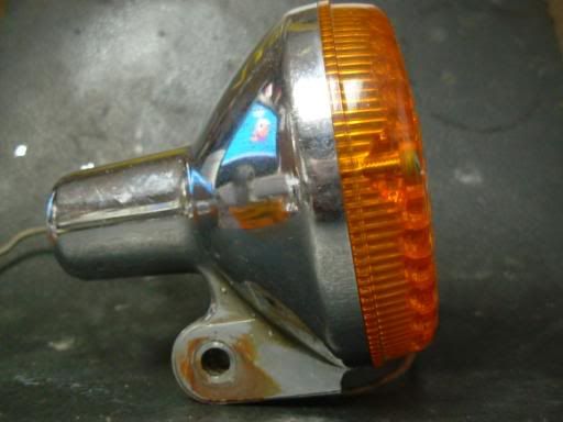
and this is what was inside:
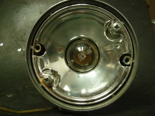
with the reflector easily unscrewed:
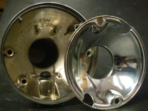
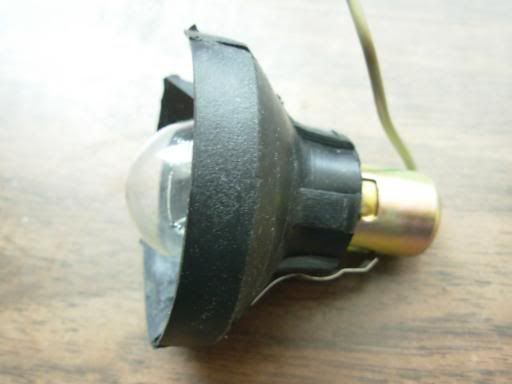
and the lamp assembly accessible. Note the lamp unit is grounded via a contact strip that touches the shell (at bottom):
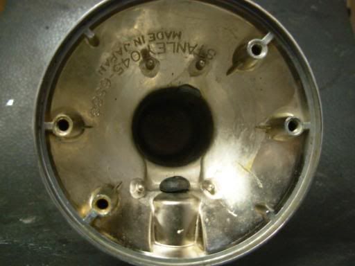
leaving the empty shell. I cut off the bullet connector so I could remount the lamp easily if I decide to (easier to reattach a bullet than to splice the wire). If you cut the original wire right at the lamp socket, you can use it for the LED array, I chose to use a new wire. Empty shell, just needs a washing:
The amber cover has to be broken off the LED marker, it's glued on. This reveals the inner workings. The chromed plastic reflector array is pretty neat, but isn't needed in the Stanley housing:
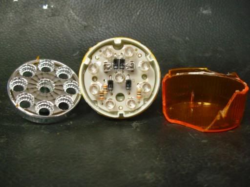
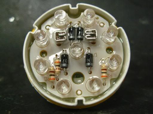
The module, front view showing the circuitry (three strings of three LEDs and the diode bridge) with a conformal coating that keeps moisture out:
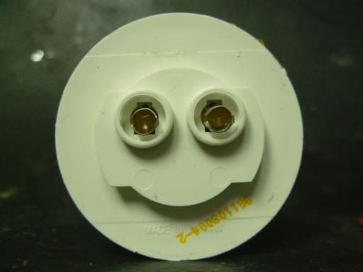
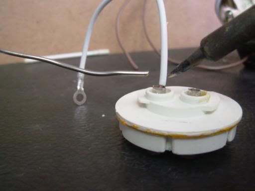
And the rear with two bullet females and the twist-in mounting adapter:
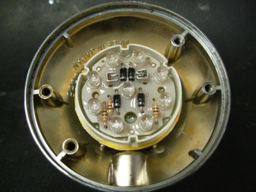
Now to test fit. You can see that the module fits really nicely but can't see that it sits flat on four pins in the Stanley housing. You may be able to see that the centre LED is a bit off centre - the module hits the housing where the mounting part meets the housing:
The LED module has a circuit board set in a plastic shell. The shell has to be trimmed a bit to centre the middle LED, so that the light pattern is optimized when the lens is fitted. I used large side cutters, you could file it for a cleaner edge:
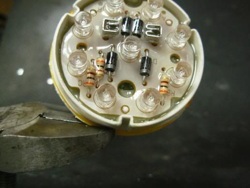
Trimmed:
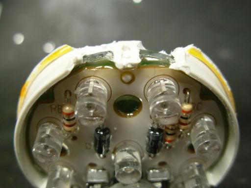
Now the middle LED can sit dead centre with the module sitting flat on the four pins:
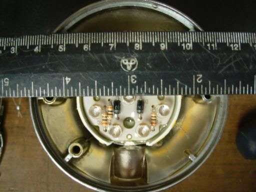
So now for wiring. The module has a diode bridge built in so polarity is unimportant. I cleaned out the bullet females in the module with a Q-tip then soldered on the wires. The included harness has a white wire with a nice ring terminal that will attach using one of the reflector mounting screws:
The power wire has to go through the grommet in the Stanley housing before soldering.. if you forget then you'll be redoing it:
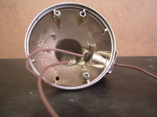
Now pull the power wire back and arrange the wires so the module will sit down on the pins. Then you have to hold it in - I decided to glue it in with black silicon rubber. You could just clamp it down, I had to make clamps anyway to hold it down and centred while the rubber set. The clamps would have to be better to really hold it firmly without the rubber though, these are just a temporary fixture. Both the shell and module should be cleaned thoroughly before gluing - I used pure isopropyl alcohol:
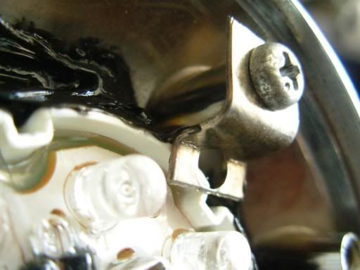
Clamped down with silicon applied:
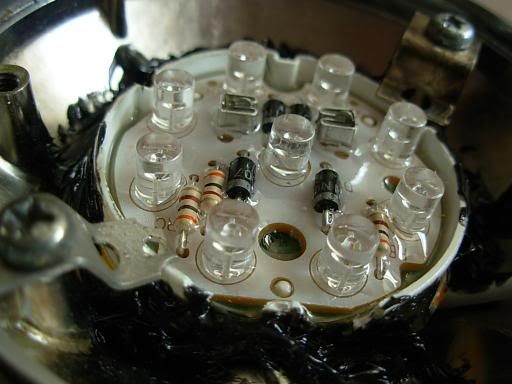
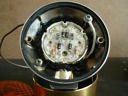
Inner workings complete, the ground wire connected with one of the original reflector mounting screws:
Now for the real test! With the lens attached and 14V DC applied, the light is quite bright but not as bright as the original bulb. I have no way to indicate in a picture or objectively measure the brightness, but it's quite visible in daylight.
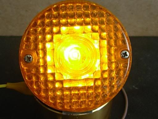
I have a 3 terminal electronic flasher so the reduced load doesn't kill the flashing. The flasher does, however, go to a fast-flashing speed meant to tell you that a bulb has burnt out. I like this fast flash - I think it's more attention-getting than the normal speed.
Anyway.. eight bucks and two days (the rubber needs several hours to set) and I have LED rear turn signals. If I come across a way to convert the front units and preserve both the marker and signal functions, I'll post it too (unless this get mercilessly flamed as useless information).
Dave