So here's a bit of an update on where I'm at for the double gauge I'm building. I thought I could integrate my oil pressure gauge into the assembly but after much consideration I decided against it.
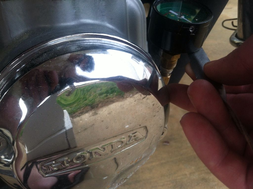
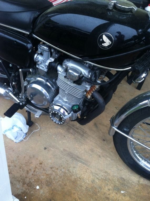
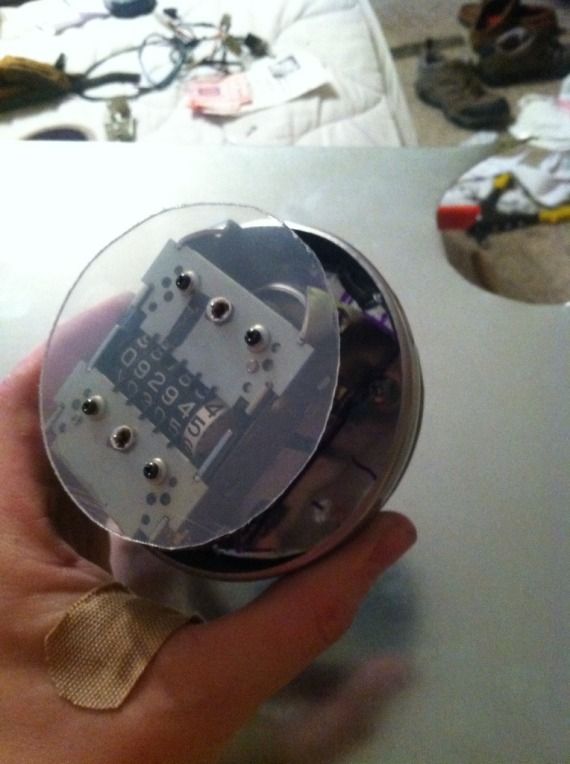
I became sidetracked when I relocated the oil psi gauge down near the points cover... I decided to combine the oil pressure gauge mount with a little point cover window because I've always liked being able to see the points moving and watching them spark at night.
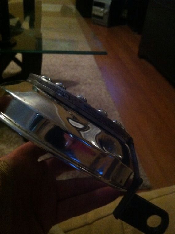
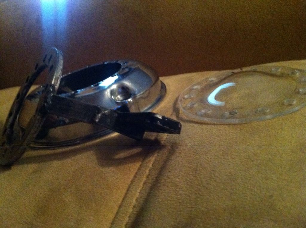
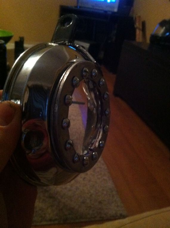
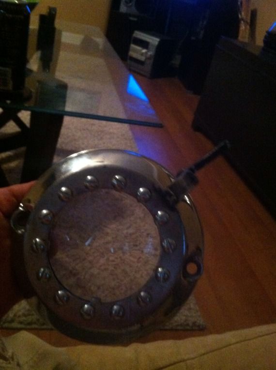
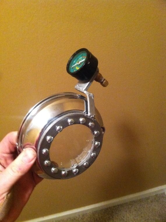
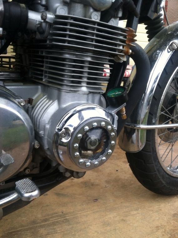
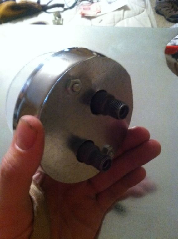
The ring I used is some sort of wheel spacer I found at the local Napa parts depot. Obviously I cut a hole in the points cover. Sandwiched between the ring and the chrome cover is a circle cut from acrylic. I soon learned keeping the acrylic flat it would contact the shaft on which the spark advance mechanism mounts. So I heated up the entire assembly in the oven and molded the acrylic over a convex form (a glass headlight projector).
*When judging my craftsmanship, do note that I was limited by the fact that my angle grinder #$%* the bed a week ago, so I wasn't able to clean up my welds or make precise cuts in thick steel of the gauge bracket.

I haven't decided whether I like it or not, but I'll keep it for a while and see how it suits me..
Back to the task at hand.
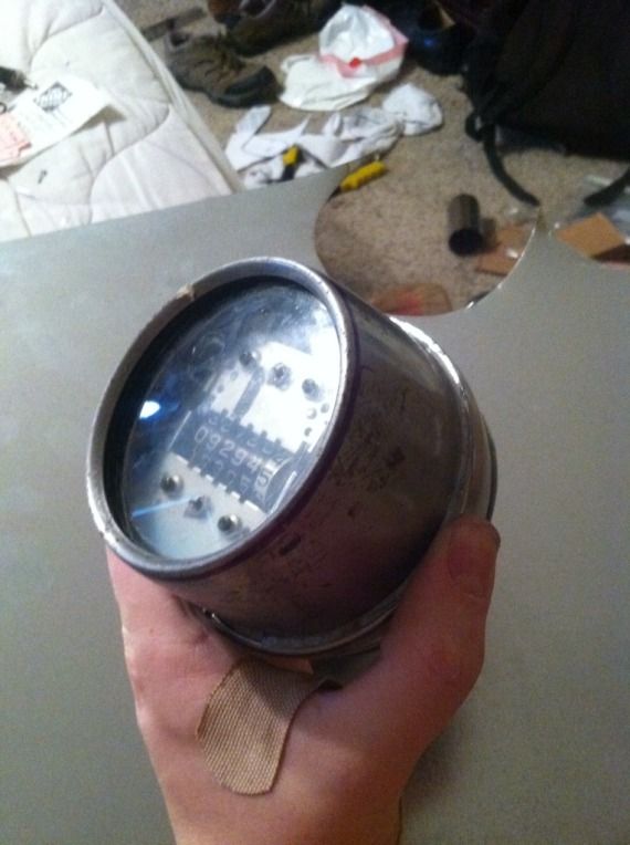
I have the housing almost complete and the acrylic for the face cut and fitted.
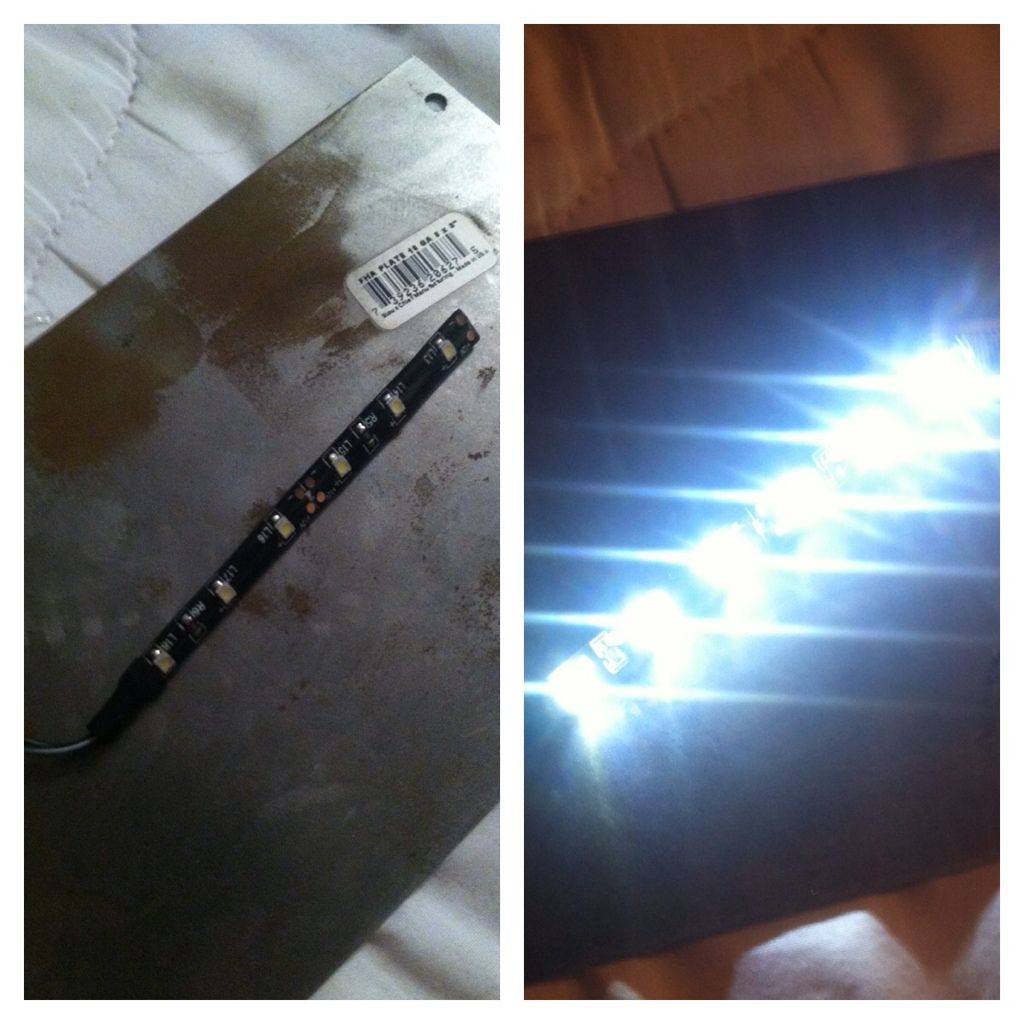
I finalized the design for the gauge face, and grabbed two little white LED strips from Wal-Mart which should light this bad boy up nice and bright.
Still left to do:
- Final paint/fit/finish work on the housing
- Make a decision on how to print the graphics for the gauge face... My inkjet printer isn't going to cut it, but finding a capable printer locally is tough because I'm not quite sure what exactly I need.
- If I ever plan to actually use the speedometer function of the gauge (and since I haven't run a speedo in quite some time) I'll need to source a cheap speedo cable as well as:
The wheel-side speedometer drive

AND the helical gear from inside the speedo drive housing

I can't remember why I ditched my old stuff or where it is now... Anybody out there got these bits laying around and want to donate?
I'll keep youse guys posted
-Davis


