Author Topic: 78 CB750F Turbo, post build review  (Read 65222 times)

0 Members and 1 Guest are viewing this topic.

Offline Bamboozler

  • Enthusiast
  • **
  • Posts: 200
78 CB750F Turbo, post build review
« on: September 29, 2009, 11:35:01 pm »
Hey all, in the following pages I'd like to document the fun, both ups and downs, I had fabbing my 750F into a force inducted machine.  Hopefully it with aid others venturing down a similar path.  

I've been around the forums for a while and post little, most of the questions I've had in the last few years I've found while searching thanks to the excellent contributions from the many of you who post.  Short history of the bike, bought it in '07 from a guy who my father works with for $450.  Didn't run, pulled and clean the carbs, got it up and running.  Noticed oil leaking from the head/jug joint and tore out the motor and replaced the head gasket and all was well.

Then the bug to turbo it came about.

I've had prior experience with turbocharging autos and was curious to see weather the bone stock motor had it in it to maintain itself with a mild amount of boost. I know its done before, even back in the 70s with Rajay kits. But with the limited amount of boosted CB info it gave me an excuse to start a fun fab project. ;D  It would also provide test bed to play with some electronic fun projects during the winter.

Today is a milestone as I fired up the bike for the first time!  That exhaust tone, its bad ass... 8)  Now comes the fuel tuning and tweaking, hopefully it won't be too painful and I can get her dialed in for some ride time before the snow falls... if I don't burn or break her up in the process. ;D  

I'll chip away at the updates as time permits and try to keep the info somewhat organized and together.

Few pics of the bike in current form.


« Last Edit: December 01, 2009, 08:03:41 pm by Bamboozler »
'78 CB750F Turbo, 101 rwhp @ 8 PSI (Project thread)
2007 Yamaha FZ1
'78 CB750F basket case crying for a resto
'78 XL250S
'78 Suk GS750E
Digital Ignition project (Project thread)

Offline bmikkalson

  • Full Member
  • *
  • Posts: 45
Re: 78 CB750F Turbo, post build review
« Reply #1 on: September 30, 2009, 01:29:37 am »
wow, way to cool.   The turbo manifold is very nice looking. 

Offline daewon774

  • Enthusiast
  • **
  • Posts: 154
Re: 78 CB750F Turbo, post build review
« Reply #2 on: September 30, 2009, 06:59:33 am »
Video with sound! Video with sound! Video with sound!  ;D ;D ;D
76' CB550
11' Ducati 848 EVO

Offline valt

  • Enthusiast
  • **
  • Posts: 235
Re: 78 CB750F Turbo, post build review
« Reply #3 on: September 30, 2009, 07:36:39 am »
How could you possibly tell us that it runs and sounds awesome but then not post a video!!!! I swear if I ever find a rayjay kit I will pay what ever money they ask for it.

Offline Bamboozler

  • Enthusiast
  • **
  • Posts: 200
Re: 78 CB750F Turbo, post build review
« Reply #4 on: September 30, 2009, 07:51:30 am »
I feel short changed myself.  I've been using the work camera to document the bike through it's stages. Last night I grabbed the camera off a work friend's desk who was done using it (I'm the keeper of the camera) and found out prior to starting the bike that the memory card was still in his computer...:(  Missed it's maiden start.  I'll try to throw a vid up soon, hoping the Cannon camera can do the tone justice.
'78 CB750F Turbo, 101 rwhp @ 8 PSI (Project thread)
2007 Yamaha FZ1
'78 CB750F basket case crying for a resto
'78 XL250S
'78 Suk GS750E
Digital Ignition project (Project thread)

Offline HavocTurbo

  • Angry little bastard of an
  • Old Timer
  • ******
  • Posts: 3,739
  • Can you tell?
Re: 78 CB750F Turbo, post build review
« Reply #5 on: September 30, 2009, 08:38:54 am »
Paging Dr. Love....

Paging Doctor I.M.N. Love.
'48 HD Panhead - Exxon Valdez
'78 CB550K - Fokker CB.3
'78 Honda CB750K - Mavrik
'80 Yamaha XS850G - Kanibalistik
09 XL883L - No Name

Offline SUELZER

  • Active
  • Enthusiast
  • **
  • Posts: 152
Re: 78 CB750F Turbo, post build review
« Reply #6 on: September 30, 2009, 01:05:35 pm »
Video with sound! Video with sound! Video with sound!  ;D ;D ;D

+1 on Vid + Sound

i was just talking to my buddy the other day about turbo-ing a bike, figured someone on here was making it a reality  ;D

how are you regulating the fuel?
« Last Edit: September 30, 2009, 01:22:43 pm by SUELZER »
1976 Honda 550F
1993 Ducati 900ss
1979 Honda 750F

Offline Bamboozler

  • Enthusiast
  • **
  • Posts: 200
Re: 78 CB750F Turbo, post build review
« Reply #7 on: October 01, 2009, 12:21:37 am »
Got some video tonight. http://www.youtube.com/watch?v=Zylsl7j-CSM As the default saying goes the vid doesn't do justice, but doesn't sound too bad (kept the audio at 44.1KHz).

Took the bike for the first ride (about 200 yards down the road and back ;D) and ran into my first fuel tuning task.  All four over flows where dumping fuel so I am going to drop the float bowl from the 17mm that they are set at to 20-21mm and see what happens.  This wont happen till earlier Oct when I'm back from vacation; I will continue when back.

Fuel regulation duties are being performed by an Automotive 1:1 bypass regulator with base pressure set to ~3psi; being fed by a MSD 2225 pump.

Thanks for the kind words!
« Last Edit: October 01, 2009, 04:55:13 pm by Bamboozler »
'78 CB750F Turbo, 101 rwhp @ 8 PSI (Project thread)
2007 Yamaha FZ1
'78 CB750F basket case crying for a resto
'78 XL250S
'78 Suk GS750E
Digital Ignition project (Project thread)

Offline Bamboozler

  • Enthusiast
  • **
  • Posts: 200
Re: 78 CB750F Turbo, post build review
« Reply #8 on: October 01, 2009, 09:05:37 pm »
To walk through the turbo build I'll start in the order that I tackled the project.  I choose the project to be a blow through setup and with that choice, using a rack of carbs stock or other wise is mandated; (fuel injection aside).  This made the decision of where the turbo would reside, due to no real convenient space under the seat where a Rajay turbo blow through setup would sit. So up front it was.  As a bonus it had shorter routing for the exhaust manifold pipes which helps to drive more thermal energy into the turbine, allows the use of an intercooler, and removes hot piping and turbine from under your arsh. :)
 
I found that placing the turbo up front on a CB does present a few challenges over other similar style bike in the 750 category (Suzuki GS750 comes to mind).  That damn oil filter housing that sticks out like a pain in the ass... ;D  It was kinda a tug of war trying to keep the turbo the lowest it could be to allow nice easy bending runners to merge into the collect.  Also, the high the turbo rides on the forward slanting front frame the closer it gets to the front tire.  As is it turned out it clearances well enough. The front tire barely missing the turbine with a fully compressed front shock and the header runners found where they needed to go.

To start the header fab a turbo was needed to build the header around. I choose to be thrifty and pull the trigger on value while hoping it wasn't going to bite back by the lack of quality that tends to follow these decisions.  Finding Chinese made turbos on ebay for $215 brand new/out the door was deciding factor.  I remember looking for similar turbos and larger for auto application around 2003/04 and finding the cheapest around $550-$600.  The smallest T3 turbo that could be found was chosen, which happened to be a T3 with the following specs... (note that the turbine exducer and inducer numbers must be backwards) .. Edit to add that I'll call myself out for failing to find a better sized T2 or T25.


Brand New - T3 Turbo Charger AR42, 48 Trim

Turbo Specification:
Maximum Horse Power    325-350 HP
Type of Cooling    Oil Cooled
Inlet Size    2.5"
Outlet Size    2.25"
Type of Bearing    WET FLOAT BEARINGS
Oil inlet Size    1/8 NTP
Type of wastegate    Internal wastegate (default 8 PSI)
Compressor    .42 AR Compressor
Compressor wheel    exducer: 60.41mm/ inducer: 43.20mm
Turbine    .48 AR Turbine
Turbine wheel    exducer: 62.86mm/ inducer: 45.74mm
Type of Flange    T3
Type of Down Pipe Flange    2.5" v-band

**90 Days Limited Warranty from the date of received & professional installation required **


Now that the turbo was in hand the next step was to lock it into its final resting spot.  To do this 2 mirrored jigs were made, one for each side of the turbo to be fastened to the turbine housing and secured to the two front frame rails.  Bar stock was used to make the jig frame and one of those pipe clamps that a ground wire secures to (found in the electrical dept. in the hardware store) was used for the clamp. After welding the them up this is what came out (see top pic below).  Excuse the welds, I was lazy and didn't change out the stainless wire for the mild steel, the two didn't want to blend together for me at all. ;D

TBC..

Turbine jig
« Last Edit: December 01, 2009, 07:30:21 pm by Bamboozler »
'78 CB750F Turbo, 101 rwhp @ 8 PSI (Project thread)
2007 Yamaha FZ1
'78 CB750F basket case crying for a resto
'78 XL250S
'78 Suk GS750E
Digital Ignition project (Project thread)

Offline Bamboozler

  • Enthusiast
  • **
  • Posts: 200
Re: 78 CB750F Turbo, post build review
« Reply #9 on: October 01, 2009, 10:00:22 pm »
With the jig locking the turbo in place, the header's runners could now be started on. Something needed to flush up and seal the copper tube ring crush gaskets and that something had to be reasonably thick, thicker than the header tube could ever be.  Also, a flange had to push the runners into the crush gaskets to seal the exhaust.  What I came up was a flange that was weld to the runners and a turned down 22mm washer that was welded to the end of the runner to seal against the copper gasket… This ended being a mistake.  (see first pic for said failed parts). ;D

One thing that I didn't realize and think through at the time is the fact that the cylinder’s #1 studs are not parallel with cylinder #2's studs... the same goes with #3 and #4.  They slightly merge away from each other.  To remove the completed header off the motor you must slide all four flanges off the head studs at the same time, when the studs diverge away from each other they start to bind on the flange holes that the studs are inserted through.  Essentially the header would never be able to come off the motor and would be locked on forever.  So back to the drawing board. Though in reality I had fabbed the runners up by the time this dawned on me. >:(

I found my solution when studying what most other custom headers posted on the internet where doing, don’t weld the flange to the runners, let it slide about the runners loosely,..duh. I found a large pipe that fit snugly into the exhaust port and match seamlessly the I.D. of the port itself.  The pipe was bought from www.metalexpress.com and had the dimensions of: O.D.=1.750", I.D.=1.375", wall=0.188". I couldn't find any pipe that fit in stainless, so mild steel it was.  I bought more flanges to replace the now scrapped flanges.  The best fitting flange that was found turned out to be a TDO5H compressor outlet flange for a Mitsubishi turbo, found at RRE http://www.roadraceengineering.com/flangesandgaskets.htm.  I could only find one other source for these guys and the other source was 2-3 times more expensive.  A little bit of drilling was needed to widen the bolt holes to fit; not much material at all.

A chunk of the pipe would fit in the exhaust port seal the gasket while the stainless runner would weld directly to this piece of pipe.  The flange’s I.D. (1.650") was smaller than the pipe’s O.D. (1.750") which would allow the flange to smack into the pipe and push it into the gasket for a good seal when fasten down. (see sencond pic)  With that in mind onto the runners…

TBC after vacation when I can get back to a computer... ;D

Failed Flanges


New Flanges

« Last Edit: December 01, 2009, 07:32:19 pm by Bamboozler »
'78 CB750F Turbo, 101 rwhp @ 8 PSI (Project thread)
2007 Yamaha FZ1
'78 CB750F basket case crying for a resto
'78 XL250S
'78 Suk GS750E
Digital Ignition project (Project thread)

Offline bucky katt

  • Old Timer
  • ******
  • Posts: 4,564
  • i am a pastafarian!
    • facebook
Re: 78 CB750F Turbo, post build review
« Reply #10 on: October 02, 2009, 12:49:21 am »
any worries about the front tire being so close to a major heat source? is there space to maybe put one of those turbo blankets and some pipe wrap on it? damn that thing sounds healthy. i love a boost ride.
Of all God's creatures there is only one that cannot be made the slave of the lash. That one is the cat. If man could be crossed with the cat it would improve man, but it would deteriorate the cat.
Mark Twain - Notebook, 1894

Offline HavocTurbo

  • Angry little bastard of an
  • Old Timer
  • ******
  • Posts: 3,739
  • Can you tell?
Re: 78 CB750F Turbo, post build review
« Reply #11 on: October 02, 2009, 09:15:58 am »
any worries about the front tire being so close to a major heat source? is there space to maybe put one of those turbo blankets and some pipe wrap on it? damn that thing sounds healthy. i love a boost ride.

Shouldn't be too bad. It's an almost exact copy of the factory Kawasaki GPZ750 Turbo setup.

I think it helps the turbo dissipate heat better being out front instead of behind the head.

Very nice bike.
'48 HD Panhead - Exxon Valdez
'78 CB550K - Fokker CB.3
'78 Honda CB750K - Mavrik
'80 Yamaha XS850G - Kanibalistik
09 XL883L - No Name

BennyBlown2v

  • Guest
Re: 78 CB750F Turbo, post build review
« Reply #12 on: October 04, 2009, 12:24:38 pm »
Very cool! 

Just a tip...  That o2 sensor isn't going to read right at idle or part throttle!  You have to remember atmospheric pressure is 14.7psi, so you have that pushing back into the exhaust, tainting the reading when not flowing enough exhaust to overcome that pressure.  I've had the same problem on my sprayed Yamaha R1 when I run a dump pipe, o2 sensor was placed exactly where u put yours, and it won't read for crap until 3/4 throttle under load.  If I were you, I would move the bung up the downpipe to line it up directly under cly 4 primary.

Offline Bamboozler

  • Enthusiast
  • **
  • Posts: 200
Re: 78 CB750F Turbo, post build review
« Reply #13 on: October 12, 2009, 11:47:51 pm »
Very cool! 

Just a tip...  That o2 sensor isn't going to read right at idle or part throttle!  You have to remember atmospheric pressure is 14.7psi, so you have that pushing back into the exhaust, tainting the reading when not flowing enough exhaust to overcome that pressure.  I've had the same problem on my sprayed Yamaha R1 when I run a dump pipe, o2 sensor was placed exactly where u put yours, and it won't read for crap until 3/4 throttle under load.  If I were you, I would move the bung up the downpipe to line it up directly under cly 4 primary.

Benny I think you might be dead nutz with that assumption.  I haven't had but two quick evenings to play with the running bike before heading on my trip, but what I noticed was that at idle the WB was pegged on lean.  With a blip of the throttle the A/F dropped from being pegged lean to just about around stoich and then headed back to lean when the idle settled back down.  I just did a bit of searching on the Innovate forums and read a thread that confirmed the same "false-lean" issue with oxygen contamination from the sensor being close to the end of the pipe.  Was your readings pegged full lean with your exhaust of exhaust bung location too?

I was thinking that it was odd that how well it was running for it to be that far off in mixture.  Also, I'm not drawing that much, if any, more air into the motor at idle from adding the turbo... the stock running bike should be sitting at ~14.7 or stoich (or so the EPA tells Honda).  And finally, my buddy has a Yami RX1 with your R1 motor (carbs), he added a turbo kit and the setup was just richen the mid jet clip positions and leave the idle and main jets stock... apples to apples *should* apply hear too; I'm hoping to find at least.

I preemptively ordered another stainless 02 bung... ;)
'78 CB750F Turbo, 101 rwhp @ 8 PSI (Project thread)
2007 Yamaha FZ1
'78 CB750F basket case crying for a resto
'78 XL250S
'78 Suk GS750E
Digital Ignition project (Project thread)

Offline JLeather

  • Expert
  • ****
  • Posts: 775
Re: 78 CB750F Turbo, post build review
« Reply #14 on: October 13, 2009, 03:41:13 am »
Are those the stock carbs, and if so how did you seal them up for the boost?

Offline Bamboozler

  • Enthusiast
  • **
  • Posts: 200
Re: 78 CB750F Turbo, post build review
« Reply #15 on: October 13, 2009, 09:18:22 am »
Are those the stock carbs, and if so how did you seal them up for the boost?

Yes they are the stock PD42A carbs.  The original rubber O-rings that sealed the choke shafts that pierced through the carb bodies were pulled, tossed, and replaced with O-rings that were slightly over sized to snug up on the shaft and against the carbs.  The same was done for the rubber and felt O-rings on the throttle shaft.  I don't have the notes in front of me, but I'll list what I.D./O.D. o-rings were used.  Pure silicone was applied to the 0-rings to help with the "sticky" return and the choke linkage was modified to help it return; the wimpy return spring couldn't overcome the added resistance.  I'll explain that better too.  A boost leak check was performed on the intake system and the system went from a leaking sieve to a tiny hiss at around 15-20 psi.  Not perfect but for what we're working with its a huge improvement from the leaky original state and should allow you to retain the stock carbs.

The original atmospheric air source hose bung was also sealed with a vac cap.  This atmospheric reference for the fuel bowls also connects to every carb by rubber tubes.  The tube bungs that connect carbs #2 and #3 were also sealed so each carb now has their own single boost reference line to keep everything equal.
« Last Edit: October 13, 2009, 09:20:09 am by Bamboozler »
'78 CB750F Turbo, 101 rwhp @ 8 PSI (Project thread)
2007 Yamaha FZ1
'78 CB750F basket case crying for a resto
'78 XL250S
'78 Suk GS750E
Digital Ignition project (Project thread)

Offline Bamboozler

  • Enthusiast
  • **
  • Posts: 200
Re: 78 CB750F Turbo, post build review
« Reply #16 on: October 15, 2009, 11:16:38 pm »
Continuing with the header fab.  After the jig that held the T3 turbine flange was in place holding the flange in its final resting place and  the exhaust flanges were snugged up on each exhaust port, fabbing the runners from the four flanges to the single T3 flange was next.  Kinda remember doing more staring than doing at this point, took awhile to figure out the order of operation in which to proceed.  What worked out was #s 2 and 3 went to the back row spots and #s 1 and 4 to the front.  

The pipe I.D. that was used was 1.5" stainless with 2.25" radius.  From what I gathered from other headers 1.5" runners seemed to be the average for a 750cc.  You could maybe gain a quicker boost response with a slightly smaller diameter pipe.  I think I bought 3 90°s and 3 180° and had very little scrap left over.  The cheapest I found was http://www.mandrel-bends.com.

The routing was performed with cutoff wheel, chop saw, die grinder, with the mig to tack the pieces together.  The idea was straight forward when making the runner, get a pipe from the turbine flange to the exhaust port flange, and try to do it with as few seams as possible if possible.  Work with one runner at a time and aim for it to dump into the T3 flange with the end of the pipe just resting on the rim of the T3 flange, but not falling into it.

After all four runners were made they needed to be merged at the collect.  Using #3 as the foundation piece it was temporarily tacked into place.  It's next door neighbor #2 in the back row was then brought in be worked on and merged into #3.  Material was moved little by little to get it to fit into place as if #3 wasn't even there. Whatever metal of #2 touched on #3 had to be removed.  Using this idea the die grinder and cutoff wheel slowly worked away material until #2 sat where it should be, then it to was temporarily tacked into place.  This followed with #1 merging into #2 and finally #4 merging in to #3.  

At this point all four runner sat where they should but there was still material the other side of each pipe that needed to be removed, which it was.  After this last step the end of each runner was in the shape of the "V", and fit next to each other ready for final tacking and welding.  

(The runners on the exhaust port flange side changed in its final design from what's shown in the 2nd pic)

Runner


Runners x4


Material removal


2 pipe merge


3 pipe merge
« Last Edit: December 01, 2009, 07:34:22 pm by Bamboozler »
'78 CB750F Turbo, 101 rwhp @ 8 PSI (Project thread)
2007 Yamaha FZ1
'78 CB750F basket case crying for a resto
'78 XL250S
'78 Suk GS750E
Digital Ignition project (Project thread)

Offline Bamboozler

  • Enthusiast
  • **
  • Posts: 200
Re: 78 CB750F Turbo, post build review
« Reply #17 on: October 15, 2009, 11:43:36 pm »
After all the merging was completed the whole works was tacked together for the last time.  There were a few places where there was a bit of a gap at the merge junctions.  In hindsight, if I had measured a few more times than I cut the gaps could have been avoided.  Right down the center of the collect was a bit wide so I tack in a wedge of pipe scrap to make it easy on Mark who did the TIG work.  In the end the extra material help fill the TIGed collect seams nicely.  

Pics pre TIG.  The extra material inside the collect will be removed and cleaned up via a die grinder after the TIG work.


« Last Edit: December 01, 2009, 07:37:37 pm by Bamboozler »
'78 CB750F Turbo, 101 rwhp @ 8 PSI (Project thread)
2007 Yamaha FZ1
'78 CB750F basket case crying for a resto
'78 XL250S
'78 Suk GS750E
Digital Ignition project (Project thread)

Offline Bamboozler

  • Enthusiast
  • **
  • Posts: 200
Re: 78 CB750F Turbo, post build review
« Reply #18 on: October 16, 2009, 12:17:20 am »
One snafu was encountered when welding the collect; which was first to get welded.  Due the amount of heat driven into the collect during welding, even with many H20 cooling cycles, Mark gave back the welded collect header (with the runners still tacked on) back for final fitment in case the runners moved.  Well they did a bit, I had to refit all four runners.. :o  A bit more cutting, tweaking, tacking and it was golden again.  I suppose stitch welds could have been hit up the length of the header to secure it, but that would be susceptible to the same.  Thinking that welding it in a jig or on the bike, at least until decently solid, would have been the ticket.  

After the collect was welded and the runners were back in alignment, a bar was tack welded across the end of the mild steel pipe to keep it in alignment.  This seemed to work because it bolted up to the cylinder head without issue after all was said and done.  Seeing it on when done made me ---> ;D, onto the next piece of the puzzle.


Pics of TIGed header.  I think Mark did a knock out job on the TIG work, I was very happy with the finished header.  


« Last Edit: December 01, 2009, 07:38:58 pm by Bamboozler »
'78 CB750F Turbo, 101 rwhp @ 8 PSI (Project thread)
2007 Yamaha FZ1
'78 CB750F basket case crying for a resto
'78 XL250S
'78 Suk GS750E
Digital Ignition project (Project thread)

BennyBlown2v

  • Guest
Re: 78 CB750F Turbo, post build review
« Reply #19 on: October 16, 2009, 11:53:54 am »
Was your readings pegged full lean with your exhaust of exhaust bung location too?

Yep!  Here is the placement of my O2 sensor on my R1 with the shorty pipe:


And with the full exhaust on its in the same spot roughly, but has 3ft of exhaust after it , where it reads perfectly fine at idle:


Enough thread jacking, sorry! haha


Again, awesome build and top quality fab; good luck on getting everything up and running perfectly!  I'm interested in what kind of power numbers this thing will put down :D

Offline Bamboozler

  • Enthusiast
  • **
  • Posts: 200
Re: 78 CB750F Turbo, post build review
« Reply #20 on: October 16, 2009, 11:10:19 pm »
Heya Benny, no problems with the jacking, feel free to do so anytime.  Sweet looking ride from what I can see.  I hope you still have it to enjoy!

Tonight I moved the O2 bung up stream right next to the turbo's V-Band flange.  However I'm not seeing a difference in A/F from its prior location; still reading full lean at idle.  But... I think that the tune is just that, full lean.  I'm going to see if I can get the idle to richen up a bit by setting the fuel mixture screws according to the procedure listed in the manual.  In the mean time I have press in slow and main jets in route.  Once the idle A/F comes down from the moon I'll be able to swap the sensor back to the original spot to see if there's a difference.  Where its at right now should not allow any outside air to reach the O2 sensor, so I belief that the gauge is telling the truth.  I'll update when I finally get to start playing with the tune.
'78 CB750F Turbo, 101 rwhp @ 8 PSI (Project thread)
2007 Yamaha FZ1
'78 CB750F basket case crying for a resto
'78 XL250S
'78 Suk GS750E
Digital Ignition project (Project thread)

Offline Bamboozler

  • Enthusiast
  • **
  • Posts: 200
Re: 78 CB750F Turbo, post build review
« Reply #21 on: October 18, 2009, 11:11:38 pm »
-oil system

Oil feed to the turbo is fed via an 18" -3AN braided line.  The oil is sourced from the service port on the right side of the motor.  An adapter bought from Ebay is installed and provides a 1/8 NPT port.  A 1/8 NPT tee from ATP turbo was acquired; 1/8 NPT male to two female 1/8 NPT.  One is for the feed and one can be used for a temp and or pressure gauge.  I happen to have Nordskog digital temp and pressure gauges that have 1/8 NPT sensors that I can temporary use later to gather oil temp/pressure data with.  The feed line fastens to a M10x1.25 to -3AN adapter that threads into the turbo's oil feed. The specs listed for the turbo on the Ebay ad noted that the oil feed threads where 1/8 NPT, but I found out after buying the adapter that they where the M10x1.25.

When the oil feed was expected to be 1/8 NPT I bought an adapter with an oil restrictor for journal bearing turbos.  The restrictor necks down the oil feed to around ~0.060-0.065 or so (depending where bought) for journal bearing turbos and larger Garrett GT ball bearing turbos and ~0.035-0.030" for the smaller ball bearing turbos.  The idea is that it restricts the max oil pressure to prevent oil from leaking pass the center cartridge's seals into the compressor or turbine.  Weather or not this is needed on a CB motor I'm not sure.  I don't know if the max oil pressure would be great enough to get past the turbo's seal or not.  I figured it would hurt to have one, other turbo bikes have used them to cure a smoking exhaust from oil pressures that forced pass their seals; as along as it doesn't starve the CHRA I'm fine with having it.  It may even help maintain better oil pressure for the rest of the motor.  In any case I was bummed when I found the threads were M10x1.25 and had to send the restrictor back.  So I welded the end shut on the stainless steel M10x1.25 to -3 replacement and drilled a 1/16" (~0.063") hole to get my restrictor.  I'll update if the turbo seizes up. ;D

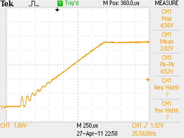
For the oil drain an accumulation chamber was added.  The idea is to save the oil pump from having to "clamp down" on the entire oil drain and feed system all the way to the motor.  By having the oil drain out of the turbo and into a chamber with a vent to the outside built in, the pump only draws vacuum from its "in" port to the accumulation chamber's drain. The vent on the chamber prevents the pump from "clamping down" any further up the line, and should allow the pump to operate with less power consumption from the CB's fragile generator.  I have yet to measure the current draw before and after plugging the vent hole to see if it works as intended or not, I'll update when I have data. There's also a tiny K&N filter on the end of the vent to prevent contamination into the oil system.

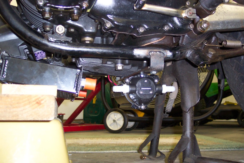
The pump that is being used is a Turbowerx unit.  The pump is a re-badged Surflo pump with what I assume to be an oil and temperature safe diaphragm.  Haven't heard much regarding the pump, but Surflo pumps are of quality which gives peace of mind.  The pump has a heat sink secured on the outside of the pump body for extra cooling capacity. Weldon also makes some nice pumps and was also considered, but are a bit more expensive.  The pump was secured under the belly of the bike with a simple bracket welded to the frame (see pic). Since the pic, two worm drive clamps were added around the pump to help secure it.   I was apprehensive at first about adding the pump and cooler under the bike, but after all was said and done there is plenty of clearance.  I would say the hardware hangs about and inch or two lower than the stock exhaust.  The clearance with the pump and cooler is actually the same as my father's HD Fat Boy, and probably higher than some sport bike fairings.

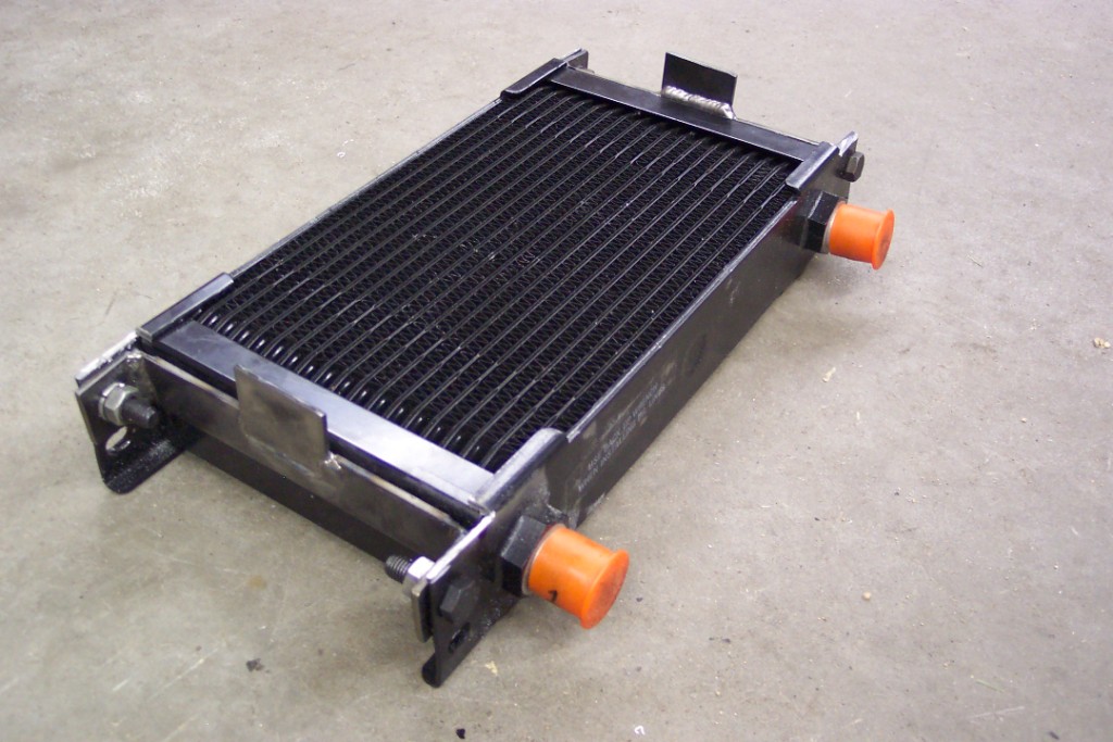
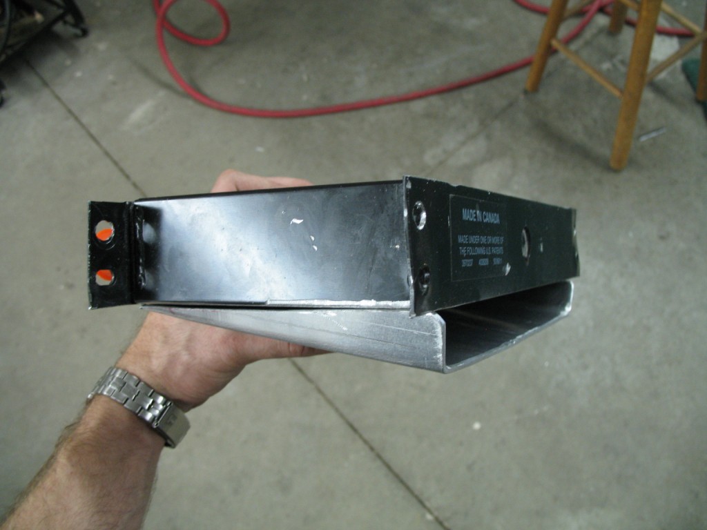
The oil cooler is a 12"x8"x2" (off the top of my head) and of unknown brand (made it Canada) that I picked up on Ebay for cheap.  It was mounted in a car but never used.  It was decided to mount it underneath to save room in front.  This gives the option of adding a intercooler above the header further down the road if and when higher boost pressures come into play.  The cooler has a simple bracket welded to the frame that keeps it secure.  An aluminum air scoop is tack welded and the seam sealed up with Rite Stuff.  The cooler's outer metal frame was a bit too thin to lay a solid bead of aluminum to seal it up, the caulk/gasket maker did a fine job.  I'm interested to see how well the ram air through the scoop will work.  I plan to take some back to back oil temp readings with the cooler as is and with it stuffed with a few rags to block the air flow; I'll update when I have data, which might not be till next riding season cuz its getting cold quick. :(

The oil is fed into the turbo, drains out of the turbo and into the accumulation chamber, is pumped out of the chamber, through the pump and into the cooler, out of the cooler and back to the motor via the #1 cylinder's intake tappet cover.  The hose that is used is a Aeroquip oil safe hose in 1/2 I.D.


oil accumulation chamber


oil scavenge pump


oil cooler


oil cooler w/scoop


feed line, oil cooler, oil accumulation chamber


« Last Edit: December 01, 2009, 07:43:49 pm by Bamboozler »
'78 CB750F Turbo, 101 rwhp @ 8 PSI (Project thread)
2007 Yamaha FZ1
'78 CB750F basket case crying for a resto
'78 XL250S
'78 Suk GS750E
Digital Ignition project (Project thread)

Offline NoXi

  • Full Member
  • *
  • Posts: 27
Re: 78 CB750F Turbo, post build review
« Reply #22 on: October 21, 2009, 09:34:42 am »
i know you already explained it. but im a little confused how you pressurised the carbs. where did you place the hoses? also how does the O2 sensor hook up to the bike and what does it do? this project is great, im sure your gonna have some insane torque numbers when your done. thanks -sam
Real men don't the need directions
2x 82' gl500's (dizzy & the brown streak)
    81' gs550 (pos)
    74ish cb750 (chop project)

Offline Bamboozler

  • Enthusiast
  • **
  • Posts: 200
Re: 78 CB750F Turbo, post build review
« Reply #23 on: October 21, 2009, 02:42:44 pm »
i know you already explained it. but im a little confused how you pressurised the carbs. where did you place the hoses? also how does the O2 sensor hook up to the bike and what does it do? this project is great, im sure your gonna have some insane torque numbers when your done. thanks -sam

Hey NoXi,

Check out the pic below.  The hoses in the blue circles are the boost compensation lines that are normally connected to the atmosphere and interconnected from one carb to another.  The two yellow circles are the same ports but I have them blocked off with vac line caps.  My figuring was to give one boost comp line to each carb to keep everything equal; the middle two carbs have two ports so I capped one.  

The other end of the boost comp line are tee'ed and, currently, then ran to the intake manifold.  When the turbo/intake sees boost pressure, it will pressurize the float bowls of the carbs too, which helps to push more fuel through the venturis to match the added air/oxygen entering the motor.  In the other turbo thread I said I wasn't going to use pitot tube. However after finding and reading more turbo related forums I think I would be making it much harder on myself to not use them.  So parts are on order and I will add them to the system.

To explain what the pitot or boost compensation tubes are (sorry if you already know).  They are small diameter tubes that are welded into the intercooler or cold pipes either facing the incoming air (parallel) or from one side of the pipe to the other with a hole or two cut into the middle for the incoming air to enter (perpendicular).  Your boost compensation lines hook up these tubes rather than the intake manifold (where mine currently are).  They don't add anything while the motor is in vacuum, but when boost pressures starts to rise they tend to provide a slight bit more pressure than when sourced from the intake due to the slightly higher pressures in the intercooler/cold pipe verses the intake manifold.  This allows you to use smaller main jets and tends to help combat a lean condition when pressures transition from vacuum to positive boost.


The wide band O2 sensor is its own entity.  Its just wired to the battery's + and - terminals.  What it helps with is being able to provide real time feedback (ok, ever so slight delay) of the air to fuel ratio.  I have a gauge in between the speedo and tach, it provides the exact air to fuel number which tells if the bike is currently running rich or lean and by how much.  Its invaluable in that it takes out a guessing game or where exactly the state of fuel tune is at.  Cuts to the chase and tells you up or down with idle jets, clip positions, main jets; no plug chopping needed.  In a boosted app its almost necessary with the pressures that are being ran in the cylinders to give you a leg up on detonation (too lean with high enough boost pressures and detonation can pop holes in pistons/break off ring lands).  I find it very handy for this project not knowing where the heck the bike's fuel tune would be after adding the turbo.
« Last Edit: October 21, 2009, 02:47:09 pm by Bamboozler »
'78 CB750F Turbo, 101 rwhp @ 8 PSI (Project thread)
2007 Yamaha FZ1
'78 CB750F basket case crying for a resto
'78 XL250S
'78 Suk GS750E
Digital Ignition project (Project thread)

Offline Bamboozler

  • Enthusiast
  • **
  • Posts: 200
Re: 78 CB750F Turbo, post build review
« Reply #24 on: November 18, 2009, 12:15:06 am »
-cold pipe/intake

The compressor on the turbo has a 2.25" outlet.  It was decided to match the outlet with a 2.25" cold pipe.  The diameter of the cold pipe probably could have been a bit smaller even, 2.0", maybe even smaller. I figure this because the compressed air exiting the compressor wheel comes out of a ~1.5" hole into the larger 2.25" hose clamp 'snout'.  In any case I'm not sure any noticeable gains would be seen with different diameters, its such a short pipe.

A Greddy Type-S copy cat blow off or bypass valve was picked up off of ebay for cheap; around $40 or so.  One of the brass carb sync hose adapters from a Morgan Carbtune is threaded into #1 carb's sync port and a vac line connects from the brass fitting to the blow off valve.  A quick explanation for those not familiar from my understanding: When the cycle is under boost, climbing in rpms toward the shift point, and the throttle is cut ensure a positive shift, the slides in the carbs close while the turbo is singing at full boost.  The compressed air runs into a wall (the slides), air flow is reduced, and compressor surging (air instability) occurs or can occur, turbo thrust bearing wear is a result.  The bypass valve provides a pressure relief valve for this compressed air to vent. The vac line has to be sourced after the slides to register less pressure than is under the BOV's piston/diaphragm in the cold pipe; this allows the valve to open.  This is why you hear the 'psssshhh' sound from turbocharged car, trucks, sleds, bikes or whatever during a shift point.

The cold pipe dumps into the intake manifold via a cast 2.25" aluminum elbow (cheap on ebay).  The manifold is 12"x3"x3" (0.125 wall) and comes out to 1770cc or roughly 2.4x the displacement of the CB's motor. The building of it was fairly simple, the aluminum plates were ordered cut to size at www.onlinemetals.com.  All that was needed were two circle saws for the drill press to cut the runner and cold pipe entrance holes.  The runners where constructed from 1.875" OD x 1.65 ID aluminum pipe; the pipe ID is a very close match to the carb's ID.  This allowed for silicone hose with a 1.90" ID to fit nicely over the runners.  However there was a bit of a gap when clamped on the carb.  I thought the silicone hose would squish around the carbs, but after the worm drive clamp cinched up they left a good sized folded gap in the silicone hose.  I found that a chunk of rubber from an inter-tube repair kit worked very well in filling that gap.  The material was thin on the ends and thicker in the middle. 4 strips were cut and wrapped around the carb mouths and took up the gap between the carbs and the silicone hose.  The manifold was taped together with masking tape and brackets for the fuel pump and regulator were fitted for welding; lastly the intake was welded.  A half hour on my friend's buffing wheel gave it a quick shine.  

Pitot tubes where added for boost compensation.  I ended up with two 3/8" tubes that face the incoming air charge and may have been able to get away with one (see turbo/supercharger thread).  In any case, the bike is responding well with the both of them.  If I end up wanting to re-tune for fun....  ::).. ;D I'll see if it could get away with only one, but I would think a increase in jet size would be needed. I guess it wouldn't be that much to plug one of the pitot tubes and split the other to the four carbs and see where the wideband sits.  In any case that's the air charge system.


Intake taped


Intake welded


Carb hose gap


Pitot tube inside


Pitot tube outside


« Last Edit: December 01, 2009, 07:46:50 pm by Bamboozler »
'78 CB750F Turbo, 101 rwhp @ 8 PSI (Project thread)
2007 Yamaha FZ1
'78 CB750F basket case crying for a resto
'78 XL250S
'78 Suk GS750E
Digital Ignition project (Project thread)