Greetings all,
My '71 CB750K1 was giving me trouble with the starter spinning and not turning the motor. Searching the forum showed that this was a problem several other forum members had faced, which was simply solved by replacing the starter freewheel springs and rollers which are cheap and easily sourced new. From what I saw of forum members' experiences, by far the most difficult thing about this is actually getting to the starter freewheel, which involves removing the alternator rotor. I finally managed to get the rotor off so I thought I'd share the method I used with forum members.
First off, I thought I'd try the screw-type puller as recommended by Honda. Forum members had few good things to say about the stock Honda screw, which has a T-bar to be turned by hand. So I got a
hex headed 20x1.5mm puller from Bike Bandit.However, this didn't shift the alternator rotor, not even when I put my air impact wrench on it. I didn't go to full torque on the air impact wrench as I was concerned about stripping the internal threads on the rotor. My wrench is adjustable from 0 to 5 (full power) and I only dared go as far as 3. The rotor was well and truly wedged fast.
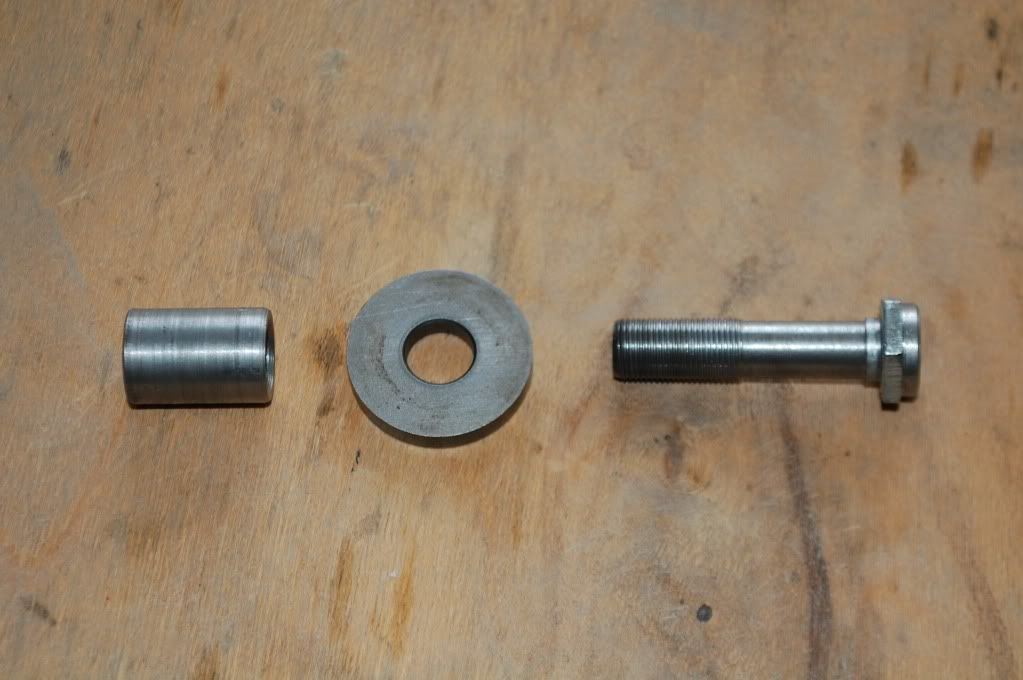
Then I started thinking about how to apply an external puller to the flywheel. I bought a suitable puller from a local tool shop but I would have to find somewhere for the central screw on the puller to push onto the crankshaft. So I got my friendly machine shop to make a bolt with the same thread as the rotor retaining bolt, but longer, and a sleeve which was a clearance fit through the rotor. That would let the bolt be tightened down on the crankshaft without actually retaining the rotor. The centre screw on the puller could then act on a dimple machined into the head of the bolt. Here is a picture of the bolt and sleeve, together with the washer which is used with the actual retaining bolt.

Dimensions:
Bolt diameter: 12mm
Bolt length: 55mm
Bolt thread length: 24mm
Sleeve external diameter: 18mm
Sleeve length: 30mm
These dimensions will leave about a 5mm gap between the rotor face and the washer.
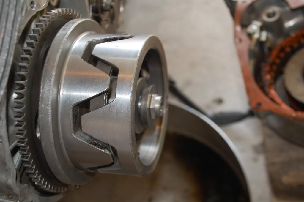
The next picture shows how it all goes together. The sleeve is inserted in the rotor opening, and the bolt is assembled through the washer and sleeve and tightened down on the crankshaft, leaving about 6mm between the surface of the rotor centre and the washer. This is the space the rotor can be extracted into. It could be an idea to fit some soft material, like a washer cut from a sheet of rubber, in this space to absorb the impact.

The next picture shows the puller assembled. I applied my air impact wrench to the puller screw, up to a force setting of 3 on the wrench. I alternated application of this system with the screw-type puller I got from Bike Bandit, to alternately pull on the rotor's periphery and on its centre. Eventually, while applying the external puller with maximum power from the air impact wrench, the flywheel separated from the crankshaft.

The last picture shows what not to do! I hadn't actually thought of using the washer to absorb the impact (duh, in hindsight) and this is what the bolt head did to the centre of my rotor... A nice, hexagonal impression of the bolt head in the rotor face! No big deal, my friendly machine shop quickly chamfered off the first couple of threads and the rotor was OK once more.

I hope some forum member finds this useful.
Best regards,
George